Ensat Inserts – Performance Details
The use of self-tapping inserts has significant advantages over pre-tapped holes, moulded-in inserts and wire thread inserts. They eliminate close tolerance holes required for tapping directly into the base material, damaged tools and low productivity resulting from moulded-in inserts and the time consuming process of placing wire thread inserts into pre-tapped holes.
The use of a self-tapping insert can result in a reduction in thread size required because of the insert’s large effective shear surface saving material and reducing cost and weight.

External Thread Interference
For a work-piece made of a light alloy, this diagram illustrates clearly that whilst correct hole sizes are important for product reliability, the Ensat 302 achieves almost maximum pull-out with only 30% external thread interference.
Pullout Resistance
In light alloy, the self-tapping steel insert resists a pullout force in excess of the yield point of an 8.8 grade bolt.


Click on a graph/diagram above to see a larger version.
Installation Procedure
- Drill hole to correct diameter, countersink if necessary.
- Screw the Ensat onto the driving tool with the cutting slot or cutting hole pointing downwards.
- Ensure that driving stud engagement into the Ensat does not exceed half the height of the cutting slot or hole
- Ensure that the insertion tool and Ensat are perpendicular to the hole.
- When using a production driver (029 series), the rotating shell must rest against the externally visible stop pins in such a way that it is driven round clockwise by the pins.
- Set depth control, where applicable, to 0.1/0.2mm below the surface of the receiving material.
- Apply reasonable downward pressure whilst driving the Ensat into the material to 0.1/0.2mm below the surface.
- Finally back the driving tool out of the Ensat. In the case of a production driver the friction lock will be released automatically, the hand tool will require the hexagon nut to be held as the drive is reversed.
Avoid “bottoming” the insert or using excessive torque as this may strip the insert out or reduce pull-out loading.
Most insertion problems arise from incorrect hole size, poor tool maintenance or bad insertion techniques. Adequate trials should always be carried out before moving to production.


Samples and low volume applications
A hand tool is available for use with a tap wrench (030/031 series).
For field repair or initial tests, a nut and bolt can be used. Ensure best possible alignment of the insert in relation to the hole.
Hole size calculation
Whilst 30% thread engagement will normally give almost maximum performance, the most appropriate hole size will vary according to the type of receiving material and the type of insert to be used.
Example: Hole size for light alloy with tensile strength of 280 N/mm2 for M8 insert type 302 is 10.8 – 11.0mm, for M8 insert type 307 is 11.1 – 11.2mm.
If difficulty is experienced in installation, it is possible to take the next hole size up without a detrimental effect. However, this should always be established by tests prior to production.
Hole design
Self tapping steel inserts can be installed into drilled or core holes. Countersinking gives a neat finish and the addition of a counter bore will facilitate insert location during installation.
A = Minimum section for through hole.
B = Minimum depth of blind hole.
Minimum Wall Thickness:
The wall thickness S is dependant upon the hardness and strength of the material being used.
Cast iron: S = 0.30 to 0.50 D
Metals: S = 0.25 to 0.50 D
(D = outside dia. of the insert)


ENSAT® - SLOTTED - 302 0 020 50
Stainless Steel - 1.4305 (Austenitic)
Description: Self-tapping with cutting slot.
Application: This is a self-tapping insert for the creation of wear-free, vibration resistant screw joints with high load capacity in materials with low shearing strength.
Hole Size: Cored and drilled hole diameters vary dependent upon the material. Please consult our technical department for a precise recommendation, to ensure optimum production conditions. Sizes given are for guidance only.
Hole Design: The hole design information is intended to indicate the approximate dimensional requirements for satisfactory installation of the insert. They should not be specified for production tooling without prior consultation with our Application Engineering Department - we accept no responsibility should the use of this information without consultation result in product failure. Please call our application engineers for assistance +44 (0) 1789 206600
Installation: Self-tapping using a hand tool or reversible drive mechanism. Tappex offer pneumatic reversible tools mounted in a Tappex FlexiArm. In certain hard materials, the slotted end of the insert can close down making it unsuitable for through bolting. In this instance a Ensat - SB is recommended. This insert is suitable for installation into metal alloys, plastics and wood.
Hole Design
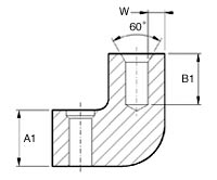
| Blind Hole B1: | 8.00 mm |
| Hole Diameter C (Alloys): | 4.20 mm-4.30 mm |
| Hole Diameter C (Plastics): | 4.10 mm-4.20 mm |
| Through Hole A1: | 6.00 mm |
| Wall Thickness W: | 1.80 mm |
Insert Design
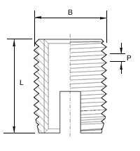
| Diameter (external) B: | 4.50 mm |
| Length L: | 6.00 mm |
| Part No.: | 302 0 020 50 |
| Pitch (external) P: | 0.50 mm |
| Pitch (internal): | 0.4 |
| Thread Size: | M2 |
The following are downloads relating to the Ensat range, although a downloads may also be applicable to other product ranges. General information can be found on our downloads page.
If you can’t find what you are looking for, why not try our chat facility where one of our helpful team can assist you or simply give us a ring on +44 (0) 1789 206600.
Tappex 2018 Brochure
Product brochure with overviews and descriptions of products.
Design Guide – Threaded Inserts For Plastics
Threaded Inserts for Plastics a ten point guide
Tappex Pinloc Range
Features, Dimensions and Part numbers of the Tappex Pinloc range of inserts